Need help?
Support Centre


MyKNX Store
 ETS Software
Download ETS to design, commission and manage KNX projects. Start with a free trial or choose a license.
ETS Software
Download ETS to design, commission and manage KNX projects. Start with a free trial or choose a license.
 ETS Apps
 extend your ETS workflow with focused tools for documentation, commissioning, diagnostics, and more. Visit our store and browse and browse our available ETS Apps.
ETS Apps
ETS Apps extend your ETS workflow with focused tools for documentation, commissioning, diagnostics, and more. Visit our store and browse and browse our available ETS Apps.
Image
Image
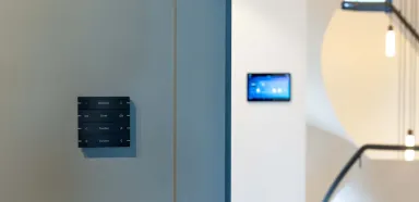






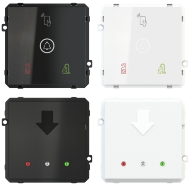

EK-TO2-TP/EK-TI2-TP
EK-TX2
ORDERING CODES
-EK-TO2-TP: KNX Secure Card Reader
-EK-TI2-TP: KNX Secure Card Holder
DESCRIPTION
The EK-TO2-TP card reader allows card reading by simply holding it close to the device, up to a maximum distance of 20 mm, enabling access based on the configured authorizations. Equipped with a backlit display and an integrated KNX bus communication module, the device combines reliable performance and refined design. It is powered by SELV voltage via the KNX bus and requires a 12–24 VAC or 12–32 VDC auxiliary power supply. Available in white or black, it is compatible with the Form, Flank, 'NF, Deep, and Surface versions with a 60 mm window, for perfect aesthetic integration into any environment.
The EK-TI2-TP card holder is designed to enable presence recognition by inserting a transponder card into a slot in the upper part of the device. It is powered at SELV voltage via the KNX bus and requires a 12–24 VAC or 12–32 VDC auxiliary power supply. Available in white or black, it is compatible with the Form, Flank, 'NF, Deep, and Surface versions with a 60 mm window, for seamless aesthetic integration into any environment.
TECHNICAL DATA
30 VDC power supply via the KNX bus
12-24 VAC or 12/32 VDC auxiliary power supply
Card reader with MIFARE 13.56 MHz RFID technology
SUPPLY
The supply includes a terminal for connection to the bus line, a plastic support for mounting in a round or square box (60 mm hole spacing), and two pairs of screws.
ACCESSORIES
- EK-TCE-10 smart card (black Ekinex® logo, pack of 10 cards) or EK-TCC-10 (customized with the customer's logo, upon request)
- Form or Flank square frame
- Square plate with 60 x 60 mm window
- Plastic adapter
Versions
EK-TO2-TP-B (black)
EK-TO2-TP-W (white)
EK-TI2-TP-B (black)
EK-TI2-TP-W (white)
FUNCTIONS AND FEATURES
EK-TO2-TP
- Backlit display with symbols
- DND (Do Not Disturb, Red LED)
- MUR (Make Up Room, Green LED)
- RFID (not backlit)
- RGB LED for generic functions, bell button with white LED
- Presence detection via bus and communication to the supervision system via KNX TP bus (twisted pair)
- KNX Secure Protocol
- Guest management of the accommodation facility based on reservation and check-in/check-out period; service user management based on time slots and passcodes
- Programmable output based on card validation or as an actuator activated by KNX telegrams. Configurable card extraction delay for courtesy light management
- Two digital inputs available for connecting a traditional button (with switching, dimming, or roller shutter/awning function) or a signal contact (e.g., window opening)
- Plastic housing
- 3K5 climate classification (indoor, dry use) and 3M2 mechanical classification (according to EN50491-2)
- Connection to the bus line via a KNX terminal
- Recessed wall mounting in a round/square box
- IP20 protection rating (installed)
- Dimensions: 80 x 80 x 35 mm
- Weight: approx. 50 g (with mounting bracket)
EK-TI2-TP
- Generic signaling LED
- DND signaling with red LED and silkscreen
- MUR signaling with green LED and silkscreen
- Freely programmable generic signaling with RGB LEDs
- RFID card reader
- Contacts Loaded
- Aux OUT contact
- Input for external DND button
- Input for external MUR button
- KNX Secure protocol
- Plastic housing
- Climatic classification 3K5 (indoor use, dry) and mechanical classification 3M2 (according to EN50491-2)
- Connection to bus line via KNX terminal block
- Recessed wall mounting in a round/square box
- Degree of protection IP20 (installed)
- Dimensions: 80 x 80 x 41 mm
- Weight approx. 50 g (with mounting bracket)
CONFIGURATION AND COMMISSIONING
A detailed description of the parameters can be found in the device application manual. ETS5 or later versions are required for configuration and commissioning. ETS application program: APEKTX2TP##.knxprod (## = version).
Note: To implement the specific access control functions for the reader and the pocket, and to program the cards, you must use the ekinex® accédo software.
To commission the device, the following steps are required:
- Make the electrical connections as indicated above
- Supply voltage to the KNX bus
- Activate the 12/24 Vac/dc auxiliary power supply
- Switch the device to programming mode by pressing the appropriate button located on the left side of the device (looking at it from the front). In this operating mode, the programming LED is on
- Download the physical address and configuration to the device using the ETS® program
Note: Unlike other KNX devices, programming with ETS is only possible if both bus power and 12/24 Vac/dc auxiliary power are provided.
| Category | Value |
|---|---|
| Catalog Item Name | EK-TX2-TP |
| Application Program Name | APEKTX2TP |
| Order Number | EK-TX2 |
| Rail Mounted | No |
| Manufacturer Website | Ekinex S.p.A. |