Need help?
Support Centre


MyKNX Store
 ETS Software
Download ETS to design, commission and manage KNX projects. Start with a free trial or choose a license.
ETS Software
Download ETS to design, commission and manage KNX projects. Start with a free trial or choose a license.
 ETS Apps
 extend your ETS workflow with focused tools for documentation, commissioning, diagnostics, and more. Visit our store and browse and browse our available ETS Apps.
ETS Apps
ETS Apps extend your ETS workflow with focused tools for documentation, commissioning, diagnostics, and more. Visit our store and browse and browse our available ETS Apps.
Image
Image






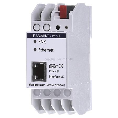

KNX / EIB IP Interface
N000401
The KNXnet/IP-Interface is used to connect a PC to the KNX/EIB network for programming via ETS or visualizations. The connection is made through LAN (IP). The IP address can be obtained by a DHCP server or by manual configuration (ETS) respectively. This device works according to the KNXnet/IP specification using the core, the device management und the tunnelling part. A typical application: the device is mounted in the sub-distribution and connected to the KNX EIB. The sub-distribution also disposes of a network connection to a remote PC. Using the remote PC the EIB KNX devices can be programmed, now, by means of LAN via ETS or the facility can be visualized with the respective software tools. The IP interface can also be used directly with a PC using a cross link cable. The PC must dispose of a valid IP configuration, i.e. at least the IP address and the sub-network must have been adjusted. The IP interface must have the same sub-network and get an IP address from this area. An example:
PC:
IP address: 192.168.1.10
Sub-network: 255.255.255.0
IP Interface:
IP address: 192.168.1.11
Sub-network: 255.255.255.0
In this particular case, the IP interface must be provided with voltage from a power unit using a cross link cable since no switch that is capable of Power over Ethernet (PoE) is available here.
Up to 5 tunneling connections possible, one tunneling connection already configured by the manufacturer with the physical address 15.15.250. Allocating or configuring further tunneling connections can be realized by pressing the Learn Key (>1sec). All other tunneling connections are then configured depending on the first tunneling connection such as:
Tunneling connection 1 (15.15.250)
Press key >1sec (flashing of Learn LED indicates that the additional connections have been activated).
Tunneling connection 2 (15.15.251)
Tunneling connection 3 (15.15.252)
Tunneling connection 4 (15.15.253)
Tunneling connection 5 (15.15.254)
If you press the key for < 1sec, the normal only Learn mode of the device (physical address KNX) is activated and this is indicated by the permanent LED light. To configurate the additional tunneling connections proceed as follows: Initial situation: Device is connected with KNX Bus and supplied with electricity, Learn LED is not on. Press and hold the Learn key. > Press Learn key until Learn LED starts to flash quickly. > Release Learn key only after flashing has stopped and LED is off again.
The remaining 4 tunneling connection received their physical addresses as described in this procedure.
To change the address area of the tunneling connection, the physical address of the first tunneling connection must be adapted. This adjustment is made by means of the ETS in the communication settings. Using the input field Physical address in the window Local adjustments the physical address of the first tunneling connection can be changed. Press the Learn Key again for more than 1 sec to configure the other tunneling connections. It must be considered that there might be address conflicts here since the addresses of the tunneling connections are not displayed directly in the ETS project! The physical addresses for the tunneling connections are always allocated starting from the physical address of the first tunneling connection upwards.
e.g.: Tunneling 1: 1.1.1 à Tunneling 2: 1.1.2, Tunneling 3: 1.1.3, Tunneling 4: 1.1.4, Tunneling 5: 1.1.5
| Category | Value |
|---|---|
| Catalog Item Name | KNX / EIB IP Interface |
| Application Program Name | N000401_IPIF_10 |
| Order Number | N000401 |
| Rail Mounted | Yes |
| Manufacturer Website | EIBMARKT GmbH |